Switchgear
In busbar trunking manufacturing, precision machining of slots, holes and bends is critical to ensuring reliable power d…
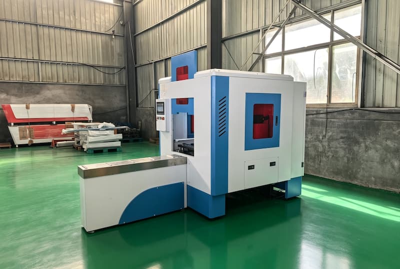
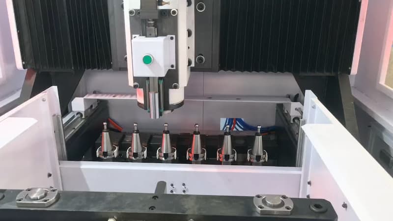
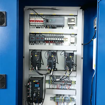
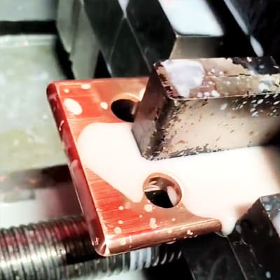
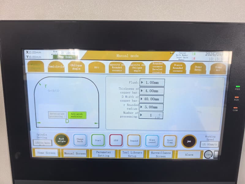
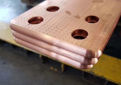
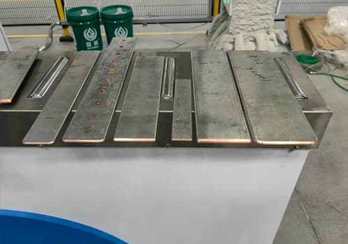
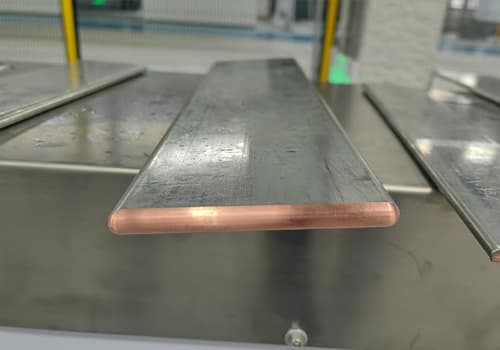
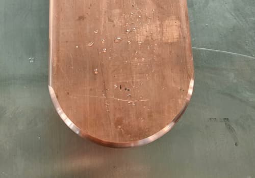
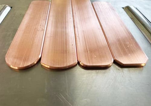
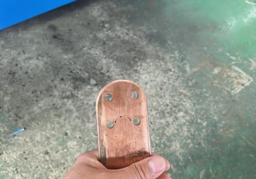
The CNC Busbar Chamfering Machine, also known as a Busbar Arc Processing Machine, is mainly designed for arc forming at the ends of copper and aluminum busbars. Unlike traditional manual grinding or hydraulic chamfering methods, the machine is equipped with six sets of cutting tools in different specifications. Driven by servo motors and controlled by a CNC system, it can perform more than 10 processing operations on busbar ends, including arcs, chamfers, semicircles, and other shapes.
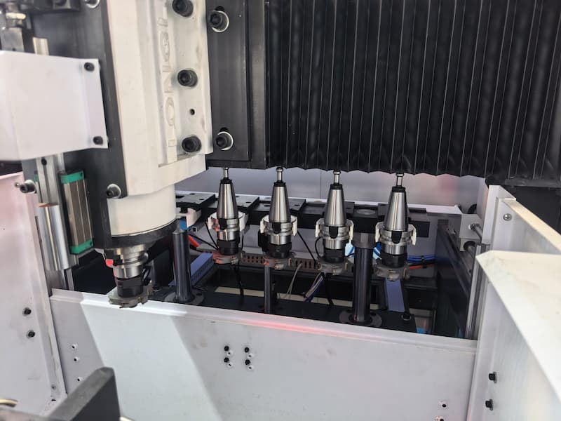
The machine features automatic clamping and centering positioning and is equipped with an automatic tool changing function. It can select the appropriate tool according to the processing requirements, enabling continuous operation from clamping and positioning to automatic tool changing and machining.
Designed for end processing of copper and aluminum busbars, the CNC busbar chamfering machine integrates CNC machining technology to optimize processing accuracy, operation mode and machining flexibility. It can meet various requirements for busbar end profiles and provide an efficient and stable end finishing solution for busbar processing.
The main specifications of the CNC busbar chamfering machine include busbar processing range, cutter configuration, spindle stroke and so on, allowing you to directly understand its processing capacity and main configuration. Below are the detailed technical parameters of the NCXJ-200 CNC Busbar Chamfering Machine.
| Item | Unit | Parameter |
|---|---|---|
| Cutting Section | ||
| Spindle Speed | rpm | 4000 |
| Motor Power | Kw | 5.5 |
| Tool Holder Model | — | BT40 |
| Feeding Section | ||
| X-axis Travel | mm | 560 |
| Y-axis Travel | mm | 350 |
| Servo Power | KW | 2 × 1.5 |
| Working Feed Speed | mm/min | 3000 |
| Cutter Parameter (Diameter) | mm | 70 |
| Number of Tools in Tool Magazine | pcs | 6 |
| Minimum Allowable Workpiece Length | mm | 160 |
| Max. Allowable Workpiece (Width × Thickness) | mm | 200×12 |
| Min. Allowable Workpiece (Width × Thickness) | mm | 30×3 |
| Total Weight | Kg | 1960 |
| Main Machine Footprint: L × W × H (with feeding rack) | mm | 3400×1600×2050 |
| Air Source Pressure | Mpa | 0.5-0.65 |
The CNC Busbar Chamfering Machine is mainly designed for forming the ends of copper and aluminum busbars. By selecting different graphic programs and cutting tools in different specifications, the machine can perform various end-processing operations, including arcs, chamfers, semicircles, irregular shapes, and more. Different cutting tools are designed for different busbar thicknesses, allowing operators to select the appropriate tool model according to the actual busbar thickness to be processed.
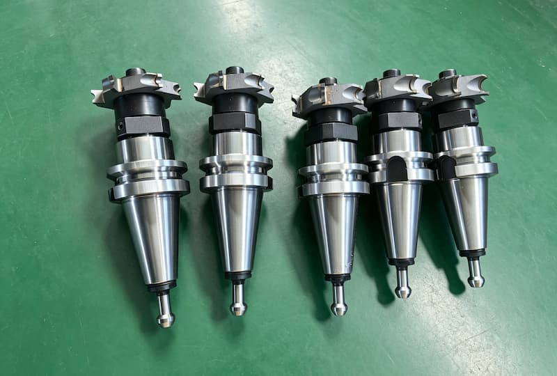
The Busbar Chamfering Machine is equipped with 6 cutting heads, which can basically cover arc processing for busbars with thicknesses ranging from 3 mm to 12 mm. The appropriate cutting head can be selected according to the busbar thickness to meet the processing requirements of busbars in different specifications.
| Name | Tool Model | Quantity |
|---|---|---|
| Tool Holder | BT40-GA70 | 6 sets |
| Tool Head | R6.5*70 | 1 set (for copper busbar thickness 11-12mm) |
| R5.5*70 | 1 set (for copper busbar thickness 9-10mm) | |
| R4.5*70 | 1 set (for copper busbar thickness 7-8mm) | |
| R3.5*70 | 1 set (for copper busbar thickness 6mm) | |
| R3*70 | 1 set (for copper busbar thickness 5mm) | |
| R2.5*70 | 1 set (for copper busbar thickness 3-4mm) |
If you have special busbar bending requirements, you may send processing drawings or specific specifications to our engineers. We will provide corresponding die solutions based on your actual machining needs.
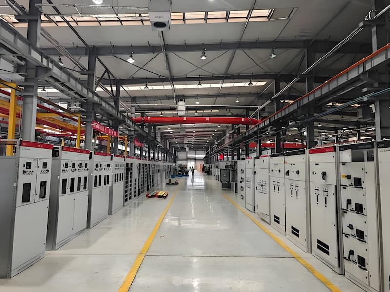
The CNC busbar chamfering machine is suitable for electrical manufacturing enterprises that need end chamfering and arc processing of copper and aluminum busbars. It can be widely applied in the following industries:
In busbar trunking manufacturing, precision machining of slots, holes and bends is critical to ensuring reliable power d…
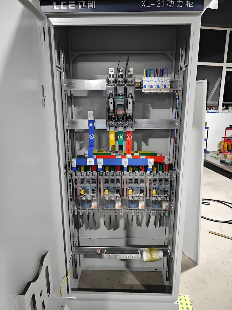
In high and low voltage switchgear, every connection point must be precisely processed to prevent arcing, overheating an…
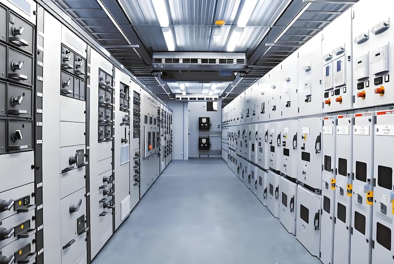
For transformer windings and connections, busbars require precise forming and hole positioning to match core layouts and…
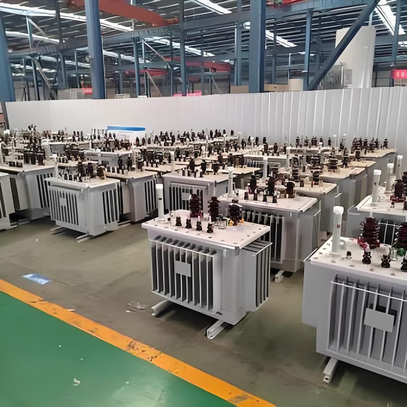
EV charging piles demand busbars that balance compact size with high current-carrying capacity, all while meeting strict…

In box-type substations, busbars must be prefabricated to fit the limited space and ensure quick, error-free on-site ins…
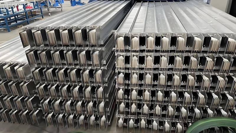
Communication cabinets and data center equipment require busbars that support high-current loads while maintaining power…
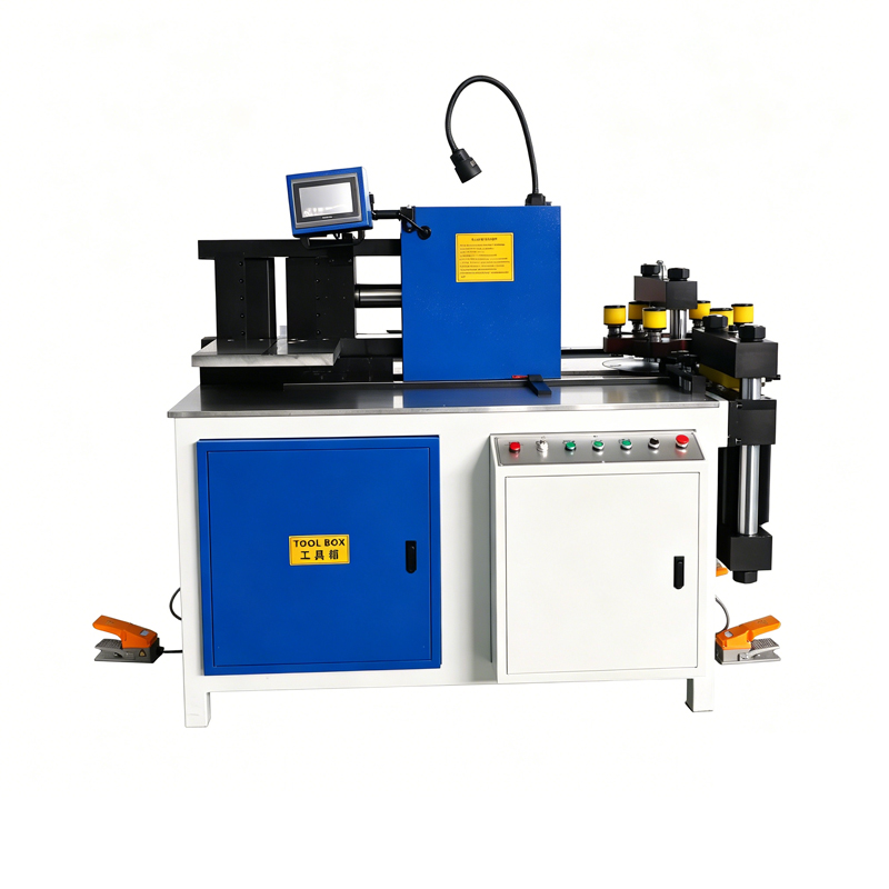
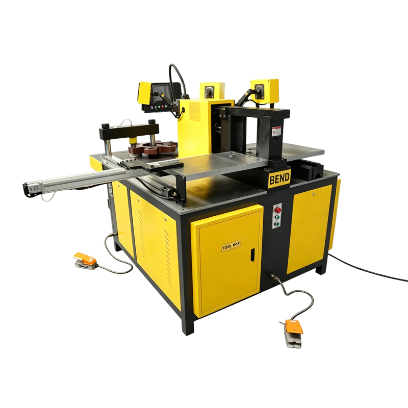
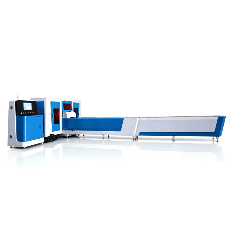
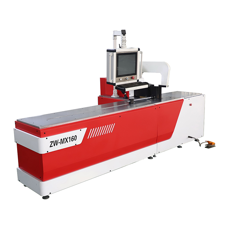
Explore related busbar processing machines for different processing requirements and applications.
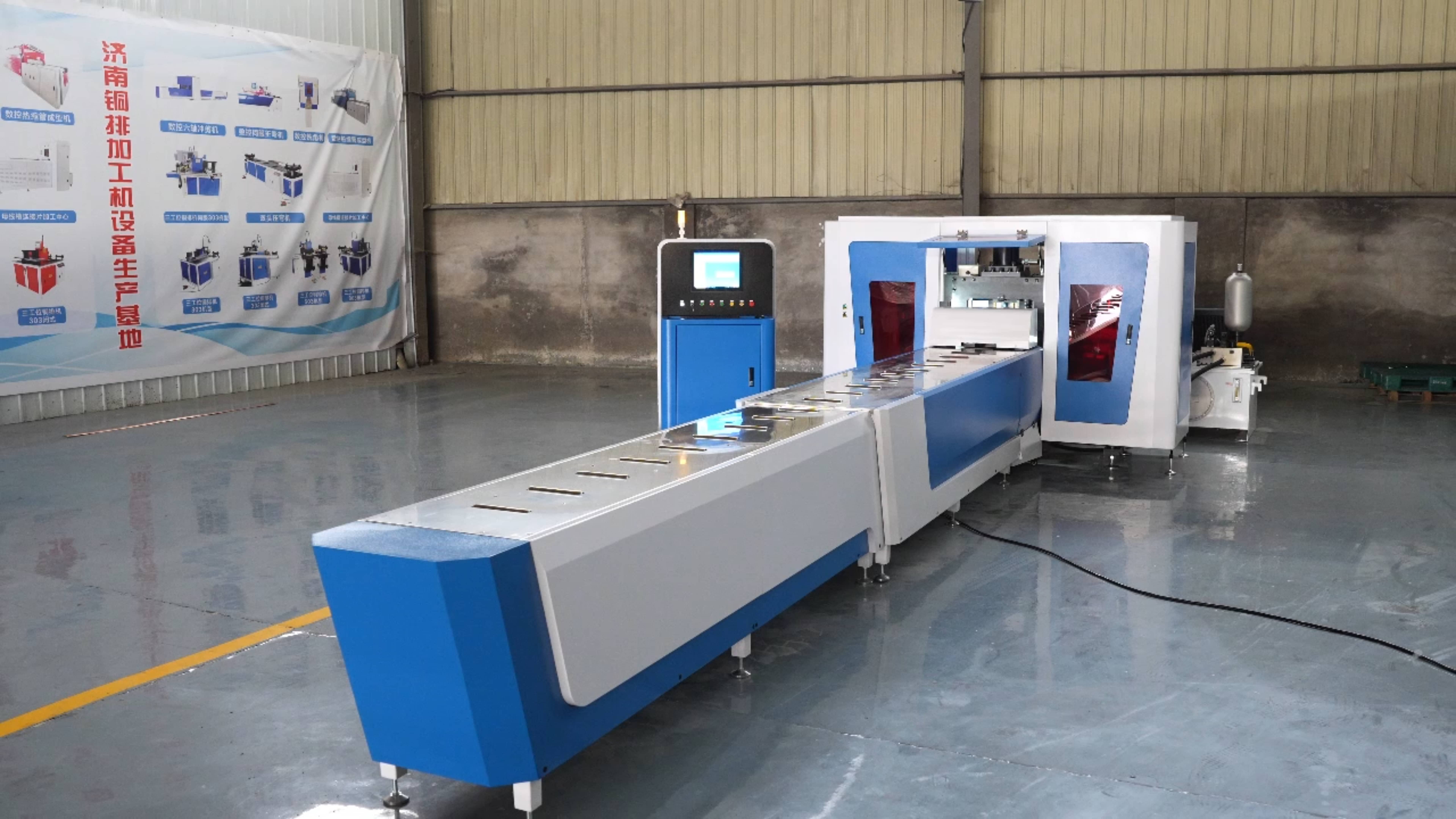
Automatic Busbar Punching and Shearing Machine Working VideoAutomatic Busbar Punching and Shearing Machine in ActionIn t…
Automatic Busbar Punching and Shearing Machine Working VideoAutomatic Busbar Punching and Shearing Machine in ActionIn t…
Automatic Busbar Punching and Shearing Machine Working VideoAutomatic Busbar Punching and Shearing Machine in ActionIn t…
Please provide your busbar material, width, thickness, and required processing operations. Our team will recommend a suitable machine based on your requirements.